Conversion Immersion
I started this project where most people would choose to start; “does this thing work with Soarer’s converter / Hasu’s converters?” These are both really great projects that have saved me tons and tons of guess work in the past. Actually, that’s probably not a fair statement. A more accurate statement would be something like, “I would totally clueless how to convert a keyboard without these projects.” Unfortunately for me, both of these avenues were dead ends for this particularly strange board.
In addition to his converter(s), Soarer also developed a Simple Logic Analyzer program. Hmm this was a new concept for me. Up until now I figured that you press some keys, magic happens inside the board, and letters pop up on the screen. I tested his Simple Logic Analyzer program with an AT keyboard I knew to work and it seemed great. Unfortunately again, when I hooked it up to the Alloy I hit a dead end and was unable to get any output.
Pinout Panic
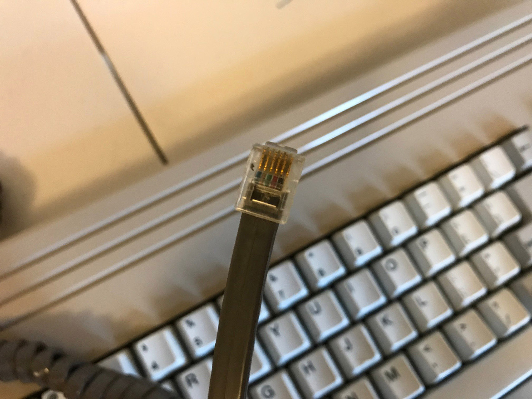
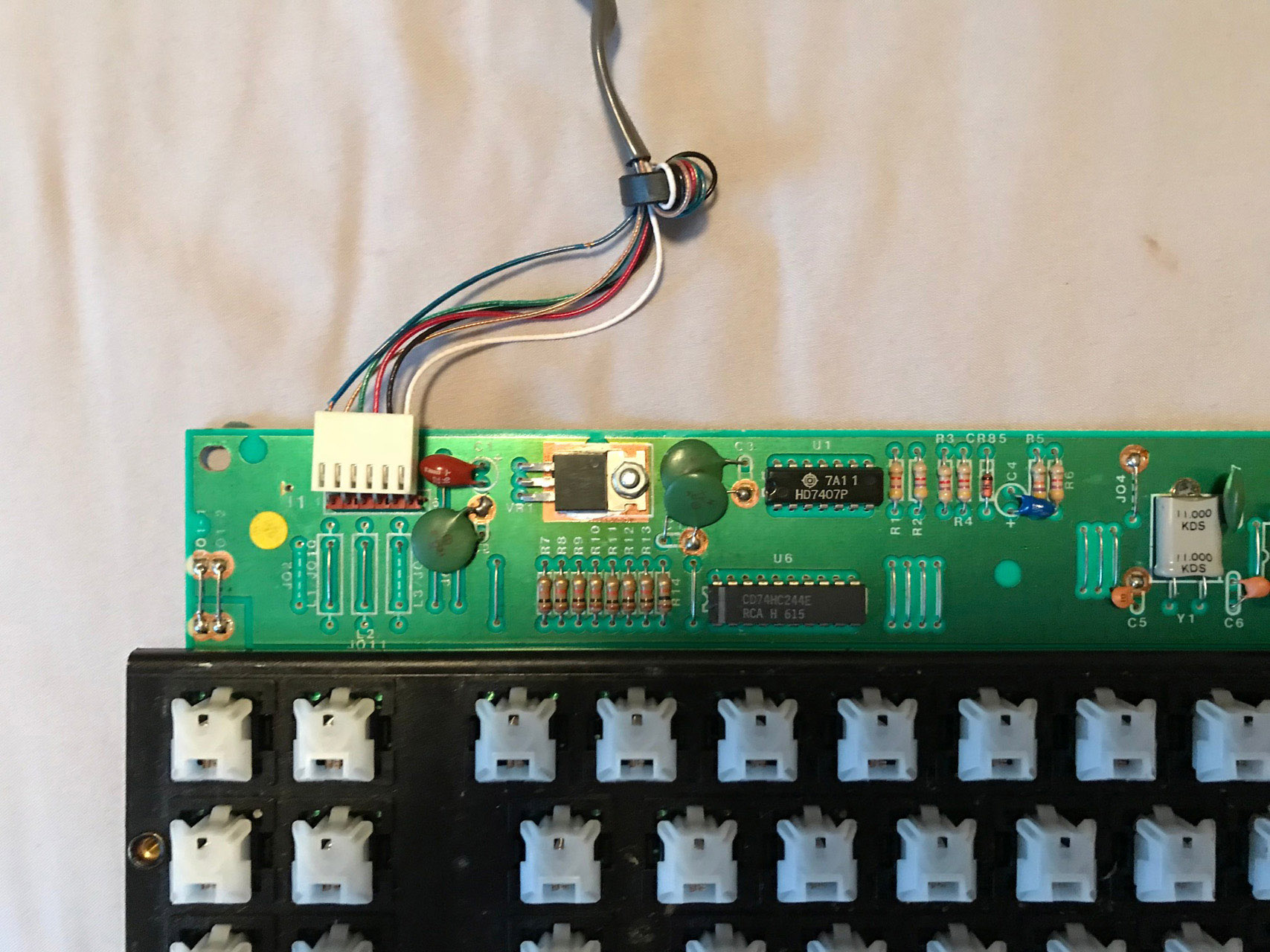
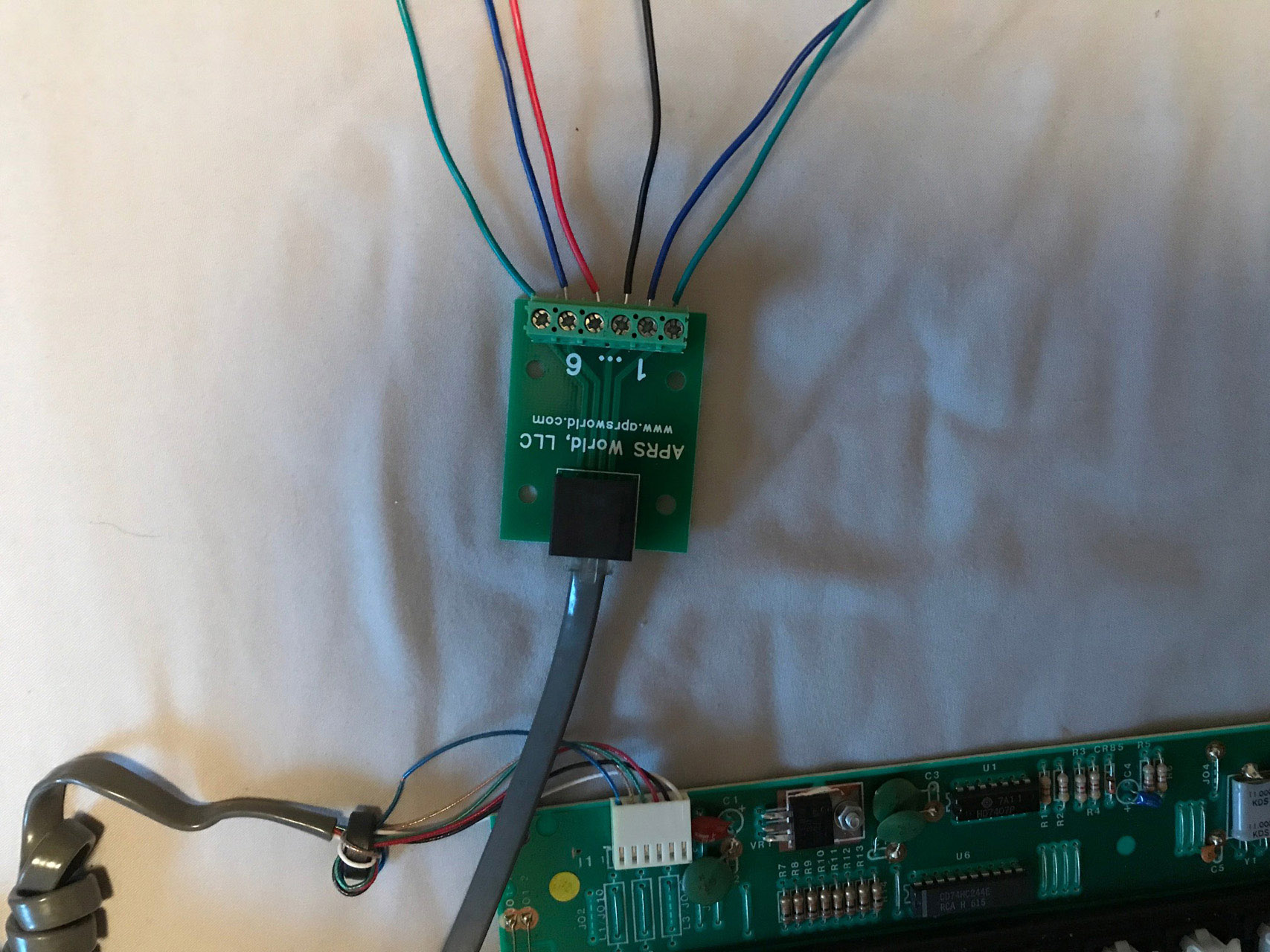
The pinout is typically supposed to be pretty simple to figure out. Vcc and GND in particular should be easy to identify. But since I’m still very new to this, I didn’t know exactly what I should be looking for. Luckily there are helpful people on the internet who took a look at my photos and informed me. It was starting to take shape as someone helped me figure out the one power line and the two ground lines. That left a few possibilities for data/clock (and maybe reset as well). I played around with this quite a bit but still couldn’t get the board to talk to me.
“Get Yourself a Real Logic Analyzer”
A member on Deskthority recommended I get my hands on a real logic analyzer; particularly one made by Saleae. I eventually did buy a Saleae (second hand), but only after trying and failing with another analyzer that was popular a few years back. I’m really blown away how easy and useful the Saleae software is to use. I’m so glad I was able to get a used analyzer for a decent price because the retail pricetag was way out of my range.
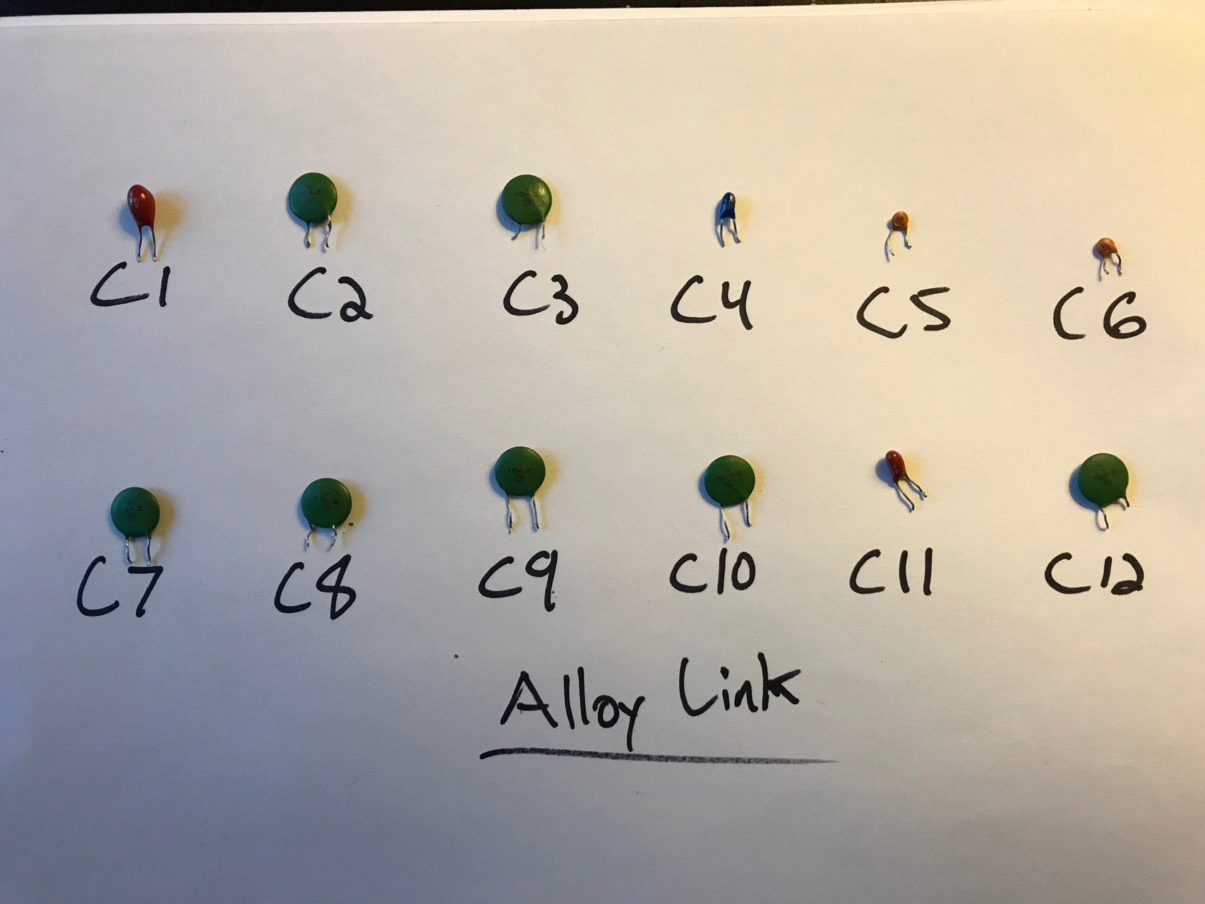
The War on Capacitors
The board still wasn’t working so I then set my sights on capacitors. Supposedly electrolytic capacitors degrade over time and go bad. Surely this had to explain why my keyboard wasn’t working! (Spoiler Alert: it didn’t). Never the less, I charged forward removing all of the existing electrolytic capacitors and replacing them with shiny new ones I bought from Mouser.
Signs of Life
At some point in this big mess I decided that maybe this isn’t a 5V device. I know basically nothing about electricity but I do know that step-up voltage regulators exists. I ordered a couple different ones from Pololu (9V, 12V). As soon as I worked in the step-up regulator, the LEDs lit up again, but this time they lit up much brighter.
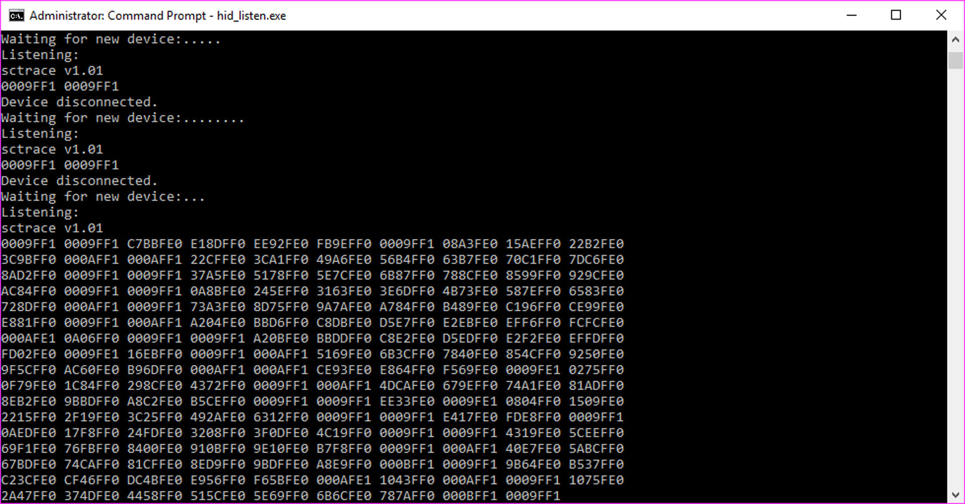
I revisited the Soarer Simple Logic Analyzer, thinking that maybe it had some hidden magic that would help me. I plugged it in and suddenly got a screen full of output!
Hmmm, first the LEDs light up, then they get brighter, now I’m getting some (jiberish) output. Maybe this isn’t a lost cause after all.
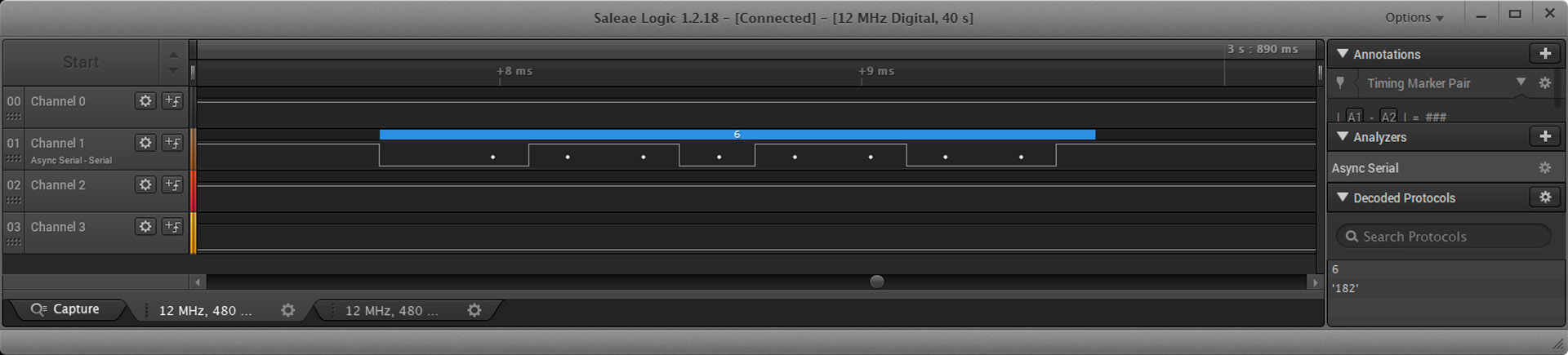
I plugged it into my real logic analyzer and got the same thing. A bunch of squigily lines at this point was very promising to see. Well it turns out that those squigily lines translated to 54 as decimal or 0x36 as hex. A friend on the forums pointed out that this is the scancode for right shift for AT and XT.
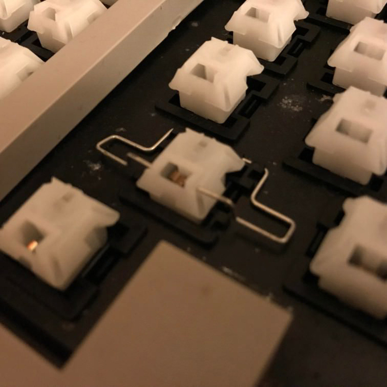
After lots of tinkering and lots more coffee, I finally found the source of my output. A stabilizer wire on left shift was pressing down the key (oops). “Oops!” but also “yay!”, and even more so “what???”. Why does this one key suddenly work?
More Mysteries
So I have a single working key now. Why don’t the other keys work? I tried each one individually and found that there were actually three working keys on the keyboard: left shift, right shift, left control. Kind of interesting that these are all modifier keys but other than that, I still can’t figure out why only these three particular keys work.
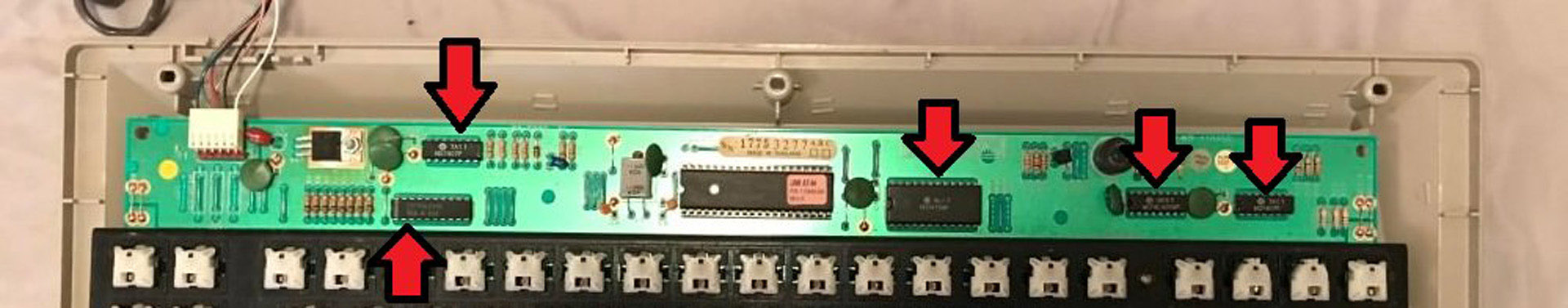
I started to look into how the switches were matrixed on the PCB and realized that things were falling into two groups (duh):
- my three keys that work
- every other key
Each of the keys from group #1 were connected to GND and each to a pin on one of the ICs. Everything else (group #2) was matrixed to two pins on the ICs (i.e. not connected to ground)
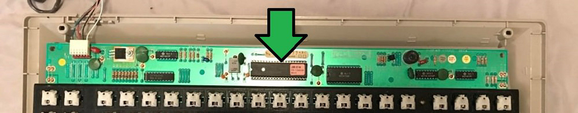
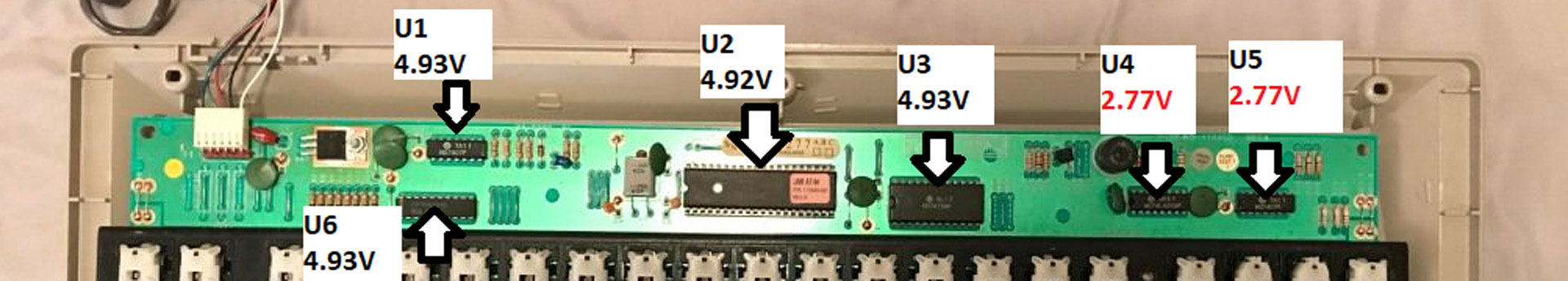
Finally I checked the voltage for each of the individual ICs. Everything was looking good until I got to the last two. Aha! Something new to look into! To be completely honest, this was probably the first thing I should have checked. And if I knew more about this stuff, I would definitely have done that. But I don’t and I didn’t and here we are so whatever.
I poked around and finally discovered the source of the voltage pull down. One of the capacitors (that I had previously waged war against and removed from the board) I neglected to solder properly to case GND. Oops again!
What’s Your Protocol?
So I fixed my boo-boo. But did it change anything? In fact, it did! Suddenly I’m able to get output on my logic analyzer no matter which key I hit on the board. But strangely, only on one line. I still have two more lines that are doing nothing. My understanding is that I should be expecting a clock signal along with my data.
Maybe this board is just weird. Maybe it has no clock? The logic analyzer has an autobaud feature to guess the baud rate. When I enabled this it went straight to 4800 which seemed promising. Okay, so if the terminal and keyboard agree on a baud rate (which at 4800 seems plausible) then we don’t need no stupid clock line anyways.
So I pressed forward sans-clock. From here things became much simpler. Testing out different key presses it became apparent that the keyboard works with XT scancodes.
“Great, so it should work with Soarer’s!”
“…No, you’ve litterally tried that a hundred times. Besides, weren’t you listening? There’s no clock.”
Conversion is Imminent
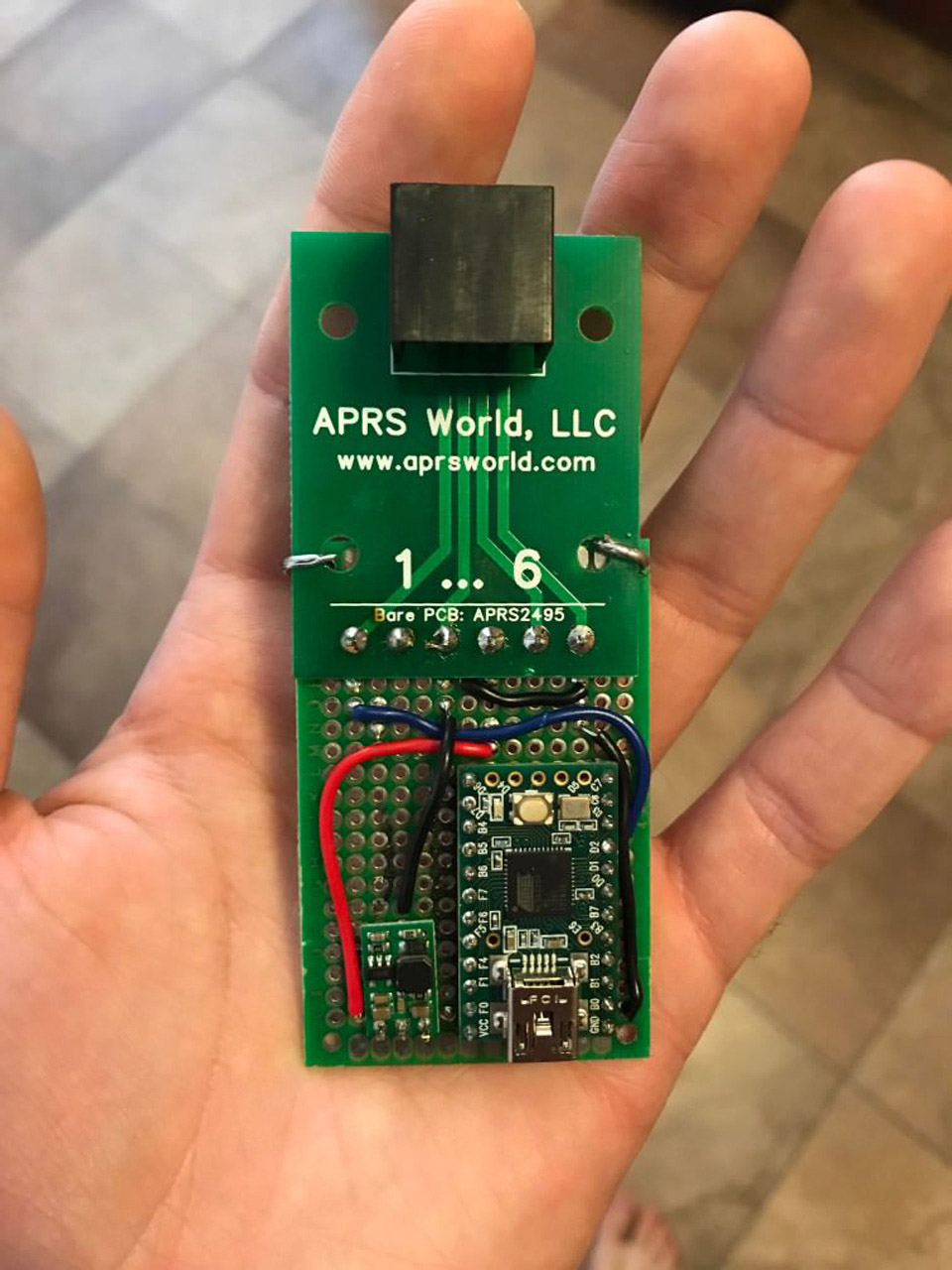
It was at this point that I thought, time to take the next leap. Now I’m not about to crack open a book and learn low level C programming. But I could probably get my head around Arduino programming if I tried hard enough.
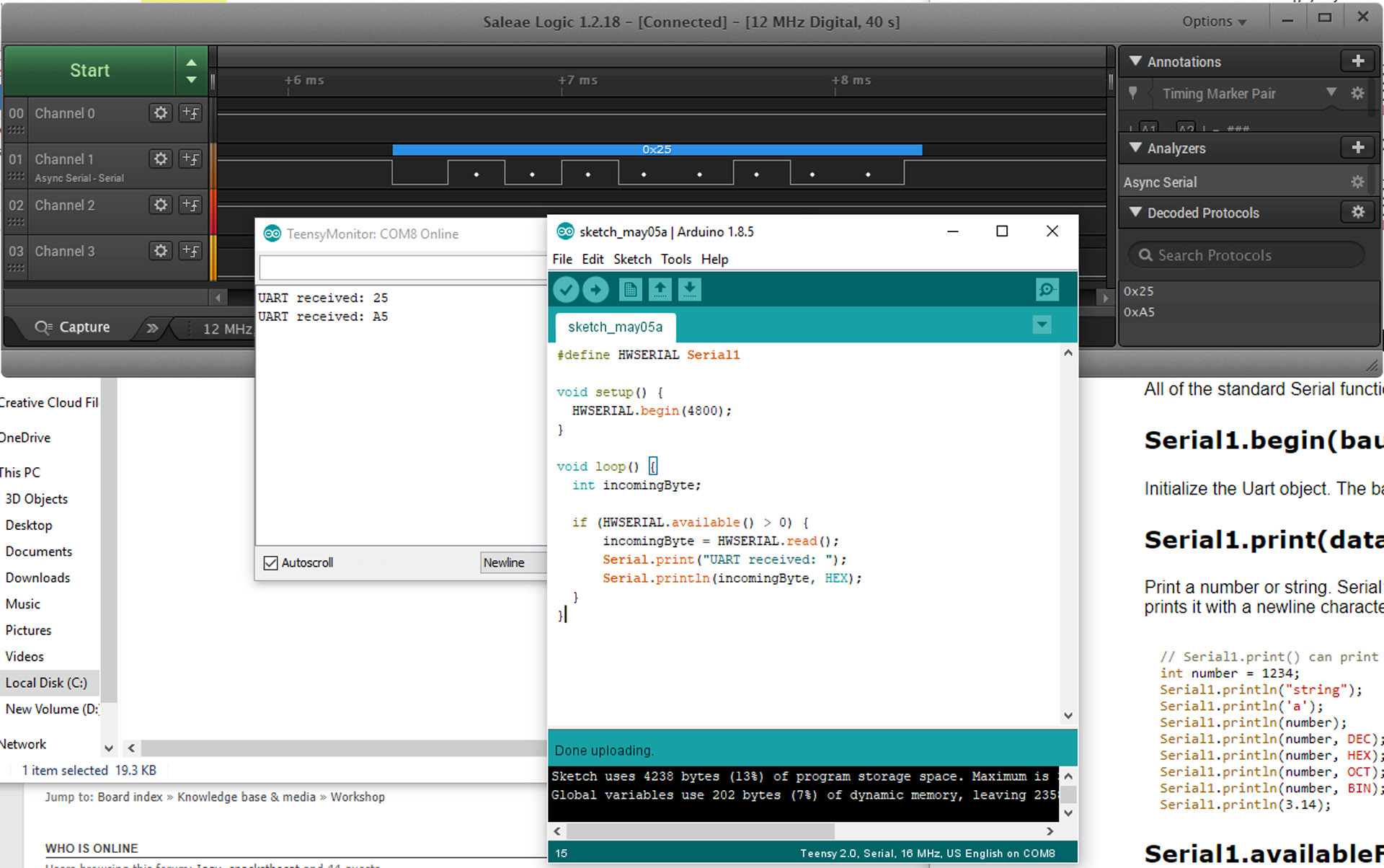
And this worked great. Working with the simple Arduino IDE was much more my speed. I was easily able to google different concepts and get a working program. While doing some of this searching, I came across Manak1n’s Open Source XT Converter, which he wrote as an Arduino sketch. This seemed perfect for my needs.
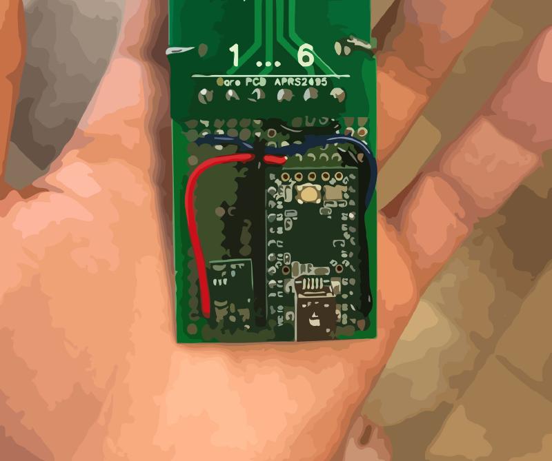
All I needed to do was modify Manak1n’s sketch to loop its reads from the serial pin instead of the clock-based reading that worked for his Model F XT. From there I was golden and the keyboard worked. Here’s the final product!